
Service
Reinforced Earth Wall Execution
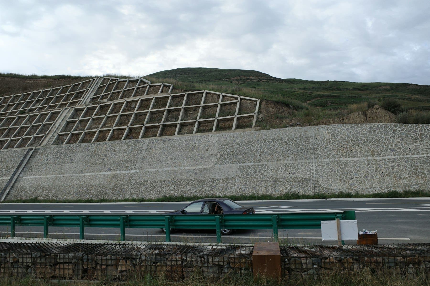
Precast-faced MSE walls and reinforced soil slopes for bridge approaches, flyovers, highways and industrial platforms.
Overview
Reinforced earth walls built layer by layer, to line and level
A reinforced earth wall — also called a mechanically stabilised earth (MSE) wall — turns compacted granular fill into a gravity structure. Layers of tensile reinforcement (galvanised steel strips, geogrids or geostraps) are placed between soil lifts and connected to a thin facing. The facing only retains the soil locally; the reinforced soil mass does the real work.
Compared with a conventional RCC cantilever wall, a reinforced earth wall is faster to build, tolerates differential settlement, needs a smaller foundation and becomes more economical as height increases. That is why it is the standard solution for bridge and flyover approaches, grade separations and elevated yards.
Typical reinforced earth wall cross-section
- Precast facing panels
- Soil reinforcement (steel strips / geogrid) at each tier
- Select granular backfill, compacted in thin lifts
- Concrete levelling pad
- Drainage and filter behind the facing
- Retained fill
- Foundation soil, proof-rolled and compacted
Schematic only — not to scale. Final design is project specific.
Benefits
Why choose reinforced earth walls
Faster than RCC walls
Panels are precast off-site and erected as the fill rises, so wall and embankment are built together instead of one after the other.
Flexible and settlement tolerant
The wall deforms as a whole with the foundation, which makes it well suited to soft or variable ground where rigid walls crack.
Economical at height
Cost grows slowly with height because there is no massive stem or base slab — savings are largest on walls above 5 m.
Good seismic performance
Distributed reinforcement and a ductile soil mass absorb ground motion far better than rigid gravity walls.
Choice of facings
Cruciform precast panels, segmental blocks, wire-mesh or wrapped geosynthetic faces — pick for appearance, durability and budget.
Controlled quality
Every lift is tested and recorded, so what is built behind the face can be demonstrated, not assumed.
Execution
How we execute a reinforced earth wall
- 1
Investigation and design check
We review the geotechnical report and verify external stability (sliding, overturning, bearing capacity, global stability) and internal stability (reinforcement length, spacing and strength) against project criteria.
- 2
Setting out and foundation preparation
Excavate to founding level, remove soft or organic material, compact and proof-roll the base, then cast a levelling pad in concrete to exact line and level.
- 3
Facing panel erection
First-tier panels are set on the levelling pad, plumbed and aligned with temporary bracing, bearing pads and joint filler. Joints are covered with geotextile so fines cannot wash out.
- 4
Select backfill placement and compaction
Approved free-draining granular fill is spread and compacted in thin lifts. Light plant is used close to the facing to avoid pushing panels out of alignment.
- 5
Reinforcement installation
Strips or geogrids are laid at design levels and full design length, connected to the panels, pulled flat and anchored. No construction traffic runs directly on reinforcement.
- 6
Upper tiers, drainage and coping
Repeat tier by tier to the top, with subsurface drainage behind the wall and surface drains above it, then cast the coping beam and crash barrier.
- 7
Quality control and handover
Density tests per lift, panel verticality and alignment surveys, material test certificates and as-built records are compiled into a handover file.
Specifications
Typical parameters
| Facing | Precast RCC panels, segmental blocks, or wrapped geosynthetic face |
|---|---|
| Reinforcement | Galvanised steel strips, HDPE / PET geogrids, polyester geostraps |
| Reinforcement length | Generally ≥ 0.7 × wall height, not less than about 2.5 m |
| Backfill | Free-draining granular soil with limited fines (typically ≤ 15% passing 75 µm) |
| Lift thickness | 150 – 300 mm compacted, depending on plant and material |
| Compaction | Typically ≥ 95% of maximum dry density, or as specified |
Values are indicative. Final parameters are set by the project design and specification.
References
Standards & guidelines
- IRC:SP:102 — Guidelines for design and construction of reinforced soil walls
- MoRTH Specifications for Road & Bridge Works — Reinforced earth structures
- FHWA-NHI-10-024 / 025 — Design and construction of MSE walls and reinforced soil slopes
- BS 8006-1 — Code of practice for strengthened / reinforced soils
FAQ
Reinforced Earth Walls: your questions answered
Read more
Related guides
Also from Terrabindz
Related services
 02
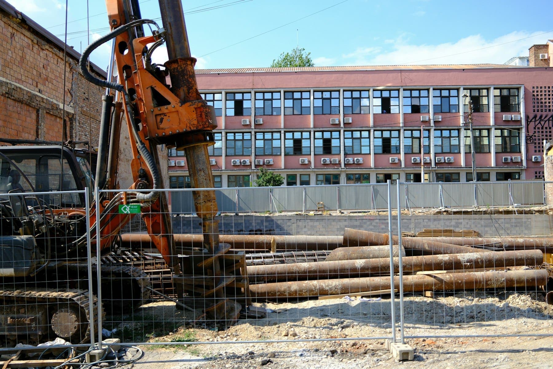
Soil Nailing
Top-down in-situ reinforcement of cuts, slopes and deep excavations using grouted steel nails and shotcrete facing.
Explore service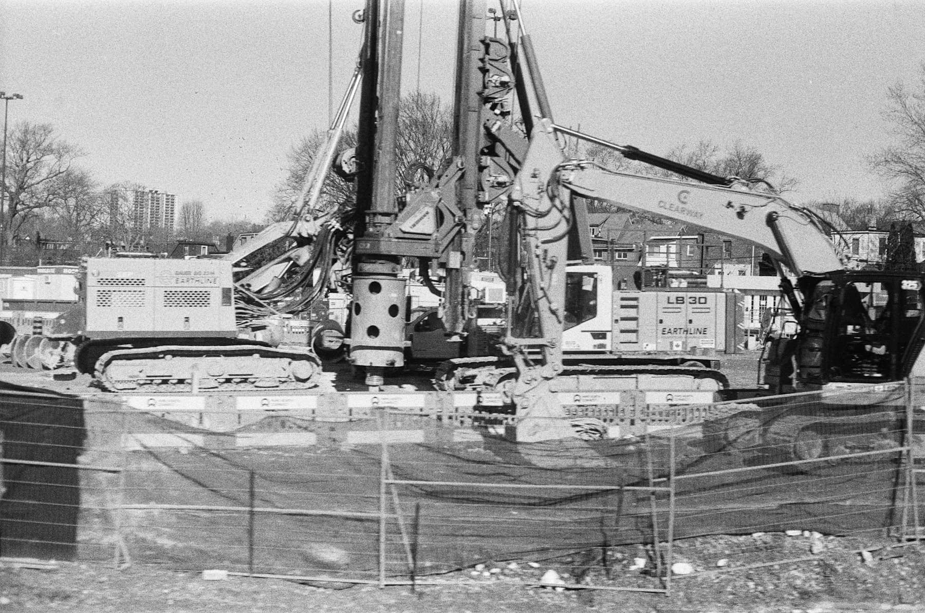 03
Ground Improvement
Stone columns, dynamic compaction, preloading with vertical drains and stabilisation for soft, loose and expansive soils.
Explore service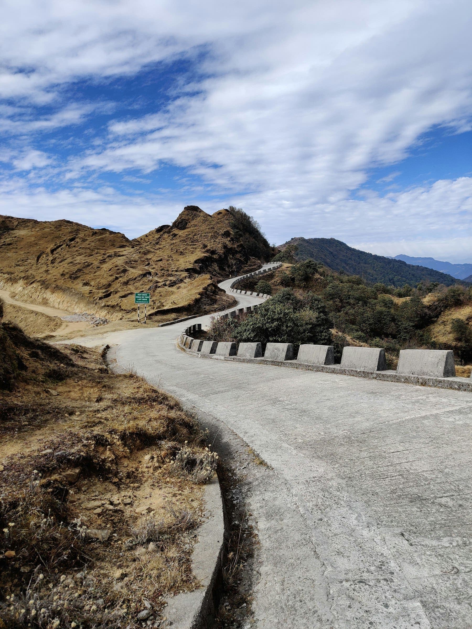 04
Slope Stabilisation
Rock bolting, shotcrete, wire-mesh rockfall protection, gabions, geogrid slopes and drainage for cut and natural slopes.
Explore service
Free consultation
Have a project in mind? Let's talk ground conditions.
Share your drawings or soil report and our engineers will respond with an approach, programme and quotation.